Once you have selected your mount, your temperature controller, and your laser driver, you are ready to set up your laser system. Proper setup of your workstation is important because it helps to ensure that your laser will function correctly and safely. Here are the important considerations you should be aware of.
FIRST, A WORD ON SAFETY
Working with lasers is potentially dangerous. A single accidental exposure to direct or reflected laser light, even at low power levels, can cause irreversible vision loss. For example, a 1-milliwatt HeNe laser shining directly into the eye can produce a power density that is 167 times that of direct sunlight!
You and your personnel should take precautions when operating your laser. At minimum, ensure that you know where your laser light and its reflections are directed, and that no one looks directly into the beam.
Laser goggles and protective enclosures such as curtains or portable panels are common methods to ensure eye protection, and many laboratories are equipped with illuminated “laser active” signs, interlocks, door switches, and other safeguards.

PROTECTING YOUR LASER FROM ELECTROSTATIC DISCHARGE
Electrostatic discharges are a high-voltage source of energy. An ESD strike damages a laser by creating a high voltage potential between two points inside the laser package. An ESD strike can deliver an instantaneous charge as high as 20,000V! This level of voltage, however brief, is sufficient to jump the electrical resistance between points on the laser package and permanently damage the laser. Protecting a laser from ESD is critical to ensuring long term operation of the laser.
SETTING UP AN ESD SAFE WORKSPACE
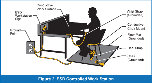
To avoid damage, ensure that your workspace is ESD-safe before removing the laser system components from their packaging, and at all times while working with your laser. Ensure that your optical table is grounded and equipped with ESD-preventive equipment.

Technicians working with your laser system should wear ESD wrist straps. If your workstation includes a rolling chair, that chair should also be grounded. (Alternatively, you may also ground yourself, each time, before handling the laser system.) Your laboratory flooring should be tile, as carpeting may produce static electricity as you walk. While not directly related to ESD risks, you should also take care to remove any ground loops from your system setup.
CONSIDERATIONS FOR WIRING THE LASER MOUNT
Ensure that your laser mount is pinned and connected correctly. The laser and the photodiode connections from the laser should be correctly wired to their relevant connections on the mount.
Some laser packages have a standard pin-out, and if you are using a commercial mount designed for that laser package, the proper wiring may already be complete (for example, most HHL packages fall into this category).
Generally, the wiring configuration will vary with the type of laser and mount you are using. For example, butterfly packages have several variations on their 14-pin package. Follow the configuration guidelines from the manufacturer to properly configure the mount for your laser.
Some laser packages have a standard pin-out, and if you are using a commercial mount designed for that laser package, the proper wiring may already be complete (for example, most HHL packages fall into this category).
HOW TO ENSURE PROPER CABLING
Cabling in another important part of a proper setup. Your cables should not consist of separate, individual wires which simply plug into their respective connectors. This can lead to induced noise, crosstalk, and inductance build-up in the cable. The best solution is to use a twisted pair for each signal path (laser, photodiode, thermoelectric cooler, and temperature sensor), bundled together with an overall cable shield.
Many laser systems dedicate separate cable bundles to the laser and TEC wiring, minimizing the signal crosstalk between the laser and TEC signals.

The use of twisted pair cabling improves modulation performance by reducing ringing and overshoot during laser modulation and fast on-off operation. For DC applications (sometimes called constant-wave applications) wherein you do not intend to modulate the laser, twisted pairs are not required, though still recommended. The overall cable should always be shielded. To ensure the efficacy of these cables, the shields must be connected to earth ground. This is typically done through the connection to the instrument.
Verify your wiring and your cables at each point: at the laser driver, at the temperature controller, and at the mount. Improper wiring in the mount or in the cables is the most common mistake in setting up a laser system.
VERIFYING THE SETUP
Before you turn on your laser system, take the time to verify your setup. First, re-check that the mount and each cable is configured correctly. Confirm the signal path through each component. This can be challenging simply because of the number of connections to be made. A typical laser will have connections for the laser and the photodiode, each with an anode and a cathode, for a total of four connections.
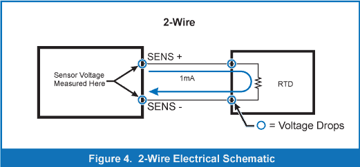
In some lasers, you may find that the photodiode and the laser share a pin for one of these connections and the connection count is reduced to three. For example, the laser cathode and the photodiode anode may share a pin, for a total of three actual pins representing four connections. If your setup includes a TEC (Peltier cooler), you will have additional connections for the temperature controller: TE-plus, TE-minus and sensor-plus and sensor-minus. Two-wire resistance sensors (such as thermistors and RTDs) are not polarized, so it does not matter which lead does to sensor-plus or sensor minus. Sensor polarity is important for LM335 and AD590 sensors, and when using four-wire sensing. Other connections may include those for four-wire sensing (sometimes found when using RTD temperature sensors), and the fan control.
A conventional, two-wire RTD uses a precise current, called a bias current, to register changes in voltage as temperature goes up or down. Cable and connectors contribute measurable electrical resistance, which contribute an offset error to the temperature reading.
To prevent this, four-wire sensing introduces a second set of sensing wires (which have no current flowing through them) and measure the voltage directly at the RTD, providing a more accurate temperature measurement.
WHY CHOOSE FOUR-WIRE RTD SENSING?
Connecting hardware in a standard, two-wire RTD temperature sensor contributes measurement error. For the most accurate temperature control, choose a temperature controller that supports four-wire sensing.


Pay particular attention to the connections related to the laser driver and the photodiode. An error in these connections may damage your laser or trigger an error message when you turn on your system for the first time.
Keep in mind that cabling configurations will vary among vendors, and some manufacturers will require you to wire your laser cable differently depending on wiring configuration of the laser and photodiode.
Second, set the appropriate limits on your laser driver and temperature controller. These limits can be found in the datasheet for your laser device or temperature controlled mount. On the laser driver, set the current and voltage limit. If the manufacturer specifies the maximum operating current, set the current limit to that value. Otherwise, set the current limit to 10% above the normal operating current of the laser so that you are not operating against the limit.
The voltage limit should be 0.5V to 1V voltage above the normal operating voltage, or the maximum operating voltage, whichever is lower.
These limits will help prevent damage to your laser due to a faulty setup and by preventing excessive current of voltage from being applied.
They will also help verify that the setup is correct by triggering when an error is detected.
These limits will help prevent damage to your laser due to a faulty setup and by preventing excessive current of voltage from being applied. They will also help verify that the setup is correct by triggering when an error is detected.
On the temperature controller, the ITE current limit should be set to the maximum TEC current rating of your laser or mount.
The temperature high and low limits should be set to 5 degrees outside your operating range, as the temperature controller will over- and under-shoot a bit when changing temperatures. This will prevent a false temperature error.
Third, set your laser driver’s current and voltage output to zero. Set the temperature set point to the desired temperature (typically 25°C) and turn on the temperature controller. Wait for the temperature to stabilize at the set point, and then turn on the laser driver. Your laser should power-on without triggering any error messages from the laser driver. Slowly ramp the laser set point up to the desired operating point. Once you have verified proper operation, there is no need to ramp the current from zero each time, simply leave it at the set point and turn the laser driver on and off.
If you are using a function generator, make sure to complete the above tests before connecting the function generator. When using a function generator, setting the current limit is critical, as it is very easy to accidentally select a modulation input that is beyond the limits of the laser. Function generators are common causes of ground loops, as the signal ground is commonly connected to earth ground. You can refer to our free whitepapers on this subject, A Guide To Identifying Ground Loops and How to Correct a Ground Loop in Your Laser System, which cover understanding, identifying, and fixing ground loop problems.
VERIFYING THE SETUP
Your first concern, as you set up your laser system, should be for the safety of your personnel and the integrity of your equipment. Laser light is a highly concentrated form of energy that may cause injury. Always be aware of where your laser light is directed. Ensure that you have mitigated the risk of static discharge and ground loops in your workstation.
Begin your verification setup process from the laser, through the mount and its connectors, through the cables, and into your instrument connectors. Examine every single signal path to ensure that everything is connected properly.
A faulty setup may damage your laser, sensors, or instruments, and will certainly demand more time and attention as you debug your connections. Be cautious and very thorough when connecting and handling your laser. The additional effort you invest now will save time and equipment costs in the future.
Setup Considerations for your Laser System and Workstation (PDF Version)