AN-009 – Using a 2-pin Laser with a 224 TEC TO-Can LaserMount
Laser TO-can laser diodes, especially blue laser diodes, have been appearing in a standard TO-5.6 and TO-9 packages, but with the laser wired differently than conventional TO-can lasers. Instead of the laser being wired such that the pins of the laser are 90° offset from each other, they are wired where the two pins are opposite each other.
For example, consider this conventionally wired TO-can:
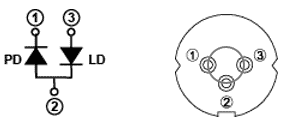
Notice that the laser is in pins 2 & 3, which are in the 3 o’clock and 6 o’clock position on the package (90° apart from each other).
Now consider this laser diode:
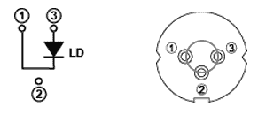
In this case, the laser pins are in the 3 o’clock and 9 o’clock positions, or opposite each other. Some packages completely omit the middle pin, leaving only the opposing pins on the package.
Sometimes called a “G” style laser package, this laser is not directly compatible with the 224 TEC TO-Can LaserMount mount because it expects a photodiode pin to be in the 9 o’clock position and a laser diode pin to be in the 3 o’clock position.
The 234B TEC TO-Can LaserMount is a mount that does have direct support for 2-pin laser diodes. By incorporating a third switch selector, the 2-pin package can be configured in the mount and standard cables can be used. The 234B TEC TO-Can LaserMount also has a much higher thermal capacity, which is often needed for the newer 2-pin lasers. However, the 224 TEC TO-Can LaserMount may be preferred because it is a smaller and lower cost mount.
MAKING THE 224 WORK WITH A 2-PIN LASER
In order to allow operation of the 2-pin laser in the 224 TEC TO-Can LaserMount, the laser must be inserted into the 224 TEC TO-Can LaserMount in a specific orientation with the switch set correctly, and a bit of re-wiring of the laser cable or building an adapter cable is required.
OPTION 1 - PURCHASING A PRE-MADE CABLE
Arroyo Instruments has available for purchase a pre-wired cable:

This cable is the same as what is described in Option 2 – Rewiring the Cable below. Follow the Configuring the 224 section below for setting the switches on the 224 mount
OPTION 2 - REWIRING THE CABLE
Modifying the cable is often the easiest, as you’re just modifying a cable you already have, so no additional parts are needed. The difficulty in modifying the cable comes from the need to do a bit of soldering to make the changes.
Normally, the laser cathode is wired into pins 4 & 5 of the DB9 connector. In this application, we’re going to route the cathode connection of the laser through the photodiode cathode terminal on the mount, so we need to move the laser cathode wire to the photodiode cathode pin on the DB9.
The instructions below assume you are using an Arroyo Instruments 1220B LaserSource Cable. If you have made your own cable, you’ll need to adjust the instructions accordingly.
- Remove the hood on the FEMALE (mount) end of the cable.
- De-solder the green (photodiode anode) and white (photodiode cathode) wires from the connector. Use electrical tape or heat shrink over each wire to ensure it does not make contact with any other wires. You can also cut off the wires if you do not intend on reconfiguring the cable back to normal.
- De-solder the black wire connected to pin 5 and the black/white connected to pin 4.
- Solder both the black and black/white wires to pin 6.
When you are finished, the cable will be wired as follows:
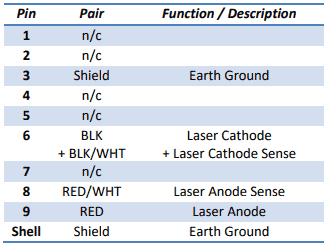
Use this cable as you normally would to connect the laser driver to the 224. Recommend you mark the cable so that it does not get confused with other standard 1220B cables.
OPTION 3 - MAKING AN ADAPTER OR REPLACEMENT CABLE
If you want to leave the existing cable alone, you can make an adapter cable, either a short cross-over cable that plugs onto the end of the 1220B cable or a full replacement cable that connects the laser driver to the 224. You just need a DB9 male and DB9 female connector (and hoods if you want them), and 20 AWG wire (smaller wire can be used, but 20 AWG is recommended – don’t go any smaller than 24 AWG). If making a short (few inches/centimeters long) adapter to plug into the 1220B cable, straight wire is okay. For longer cables, such as the full 2-meter length of the standard 1220B cable, a shielded-twisted pair cable is recommended.
Wire the connectors as follows:
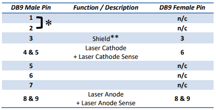
* If the new cable will be plugging directly into a laser controller (not through the 1220B cable), short (solder) pins 1 and 2 together on the DB9 Male end of the cable to close the interlock circuit.
** If your cable has a shield drain wire, it can be soldered into pin 3 of the two connectors. If you do not have a shield drain wire, pin 3 can be left disconnected.
Wherever two pins are indicated (e.g., “4 & 5”), simply place the wire between the two pins and solder across the pins with the wire creating a bridge between them. Once the adapter is complete, insert it between the end of the 1220B cable and the 224 mount.
CONFIGURING THE 224 TO-Can LaserMount
Next, set the two switches on the front of the 224 as follows:
LD Switch A position (up)
PD Switch C position (down)
The EGND (earth ground) switch can be turned on or off, depending on your application requirements. If in doubt, leave it turned off.
Finally, insert the laser diode with the anode pin in the 3 o’clock position and the cathode pin in the 9 o’clock position.
POWERING UP THE LASER FOR THE FIRST TIME
Any time you are powering up a laser for the first time in a new configuration, especially when you have new cables, you should always start in Io mode with the set point at zero.
- Connect the TEC controller and 1260B cable.
- Connect the 224 to the laser driver using the modified 1220B cable or the adapter cable..
- Configure the TEC controller for the 224, and turn it on to start temperature controlling the mount. Make sure the temperature control is functioning correctly before moving on.
- Make sure the laser driver is properly configured for the laser (current limit, voltage limit, etc.).
- Set the driver to Io (ACC)
- Change the laser driver set point to 0mA.
- Turn the laser driver on. You may see some voltage on the Vf reading or you may not, either is okay.
- Change the set point to 1mA. You should now see some laser voltage.
- Continue to increase the laser current until you have reached your target operating point. As you increase the laser current, monitor the laser voltage to verify it is operating within the expected range.
Once you’ve established proper operating by softly turning on the laser, as described above, you can leave it at the set point and simply turn the output on and off directly (no need to ramp up the current each time).